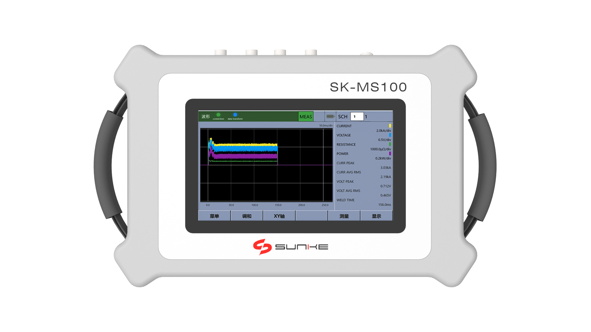
A resistance welding process can produce a visually acceptable joint while its actual electrical and mechanical conditions have already drifted. Current may be lower than expected, electrode force may change, or the weld pulse may occur at the wrong point in the sequence. A weld tester addresses this gap by measuring what happens during the welding operation rather than relying only on the finished part.
It is useful to industrial engineers because it transforms a quick, mostly undetectable welding event into quantifiable process data. Then, the data can be contrasted with reference welds or defined limitations.
A Weld Tester Measures the Process, Not Just the Finished Joint
A resistance welding monitor is essentially a measurement system for the dynamic conditions surrounding a resistance weld. Depending on its design, it can capture variables such as welding current, voltage, electrode force, electrode movement, and weld time. TWI identifies current, time, and force as core resistance-welding process variables, while more advanced systems can also examine dynamic resistance and weld expansion.
The distinction from destructive testing is important. Destructive testing examines the resulting joint by physically testing or sectioning the part. Process monitoring instead observes the conditions that produced that joint.
That does not mean a tester directly sees weld strength. Rather, it measures process variables associated with weld formation. Changes in those variables can provide an early indication that the established welding process is no longer behaving normally.
What Happens During a Measurement
During a resistance weld, electrical current passes through the electrodes and workpieces while mechanical force holds the materials together. The tester connects appropriate sensors to capture the relevant electrical or mechanical signals during this short event.
A basic device may provide a current measurement or another numerical result. More sophisticated equipment records the changing signal throughout the weld and displays it as a waveform. Weld monitors can provide real-time measurement of welding variables and are used for process development, troubleshooting, process validation, and quality control.
The measurement sequence can therefore be viewed in four stages: sense, record, analyze, and compare.
First, sensors acquire the physical signals. The equipment then converts them into usable data. Software or internal logic analyzes values or waveforms, after which the result can be compared with an established process window.
Which Welding Signals Can Be Captured?
Current is one of the most fundamental measurements because resistance welding generates heat through electrical resistance. Monitoring current can reveal whether the welding power delivered during a cycle differs from the expected condition.
Voltage provides another perspective. Measuring voltage across the welding circuit can help identify changes associated with connections, electrodes, material conditions, or other process variables. Current and voltage can also be used to derive electrical quantities such as resistance and power.
Mechanical information adds another layer. Electrode force affects contact conditions, while electrode displacement can provide information about physical changes occurring during the weld. Advanced monitoring systems can therefore combine current, voltage, force, and displacement rather than relying on a single electrical reading.
Time is equally significant because resistance welding depends on how long energy and force are applied. A current value that looks correct can still be associated with an abnormal weld if the timing or force sequence has changed.
Turning Measurements Into a Production Judgment
Raw measurements become useful when there is something meaningful to compare them against. A production team may establish a reference from known acceptable welds and define upper and lower limits for selected parameters.
Some equipment works with summary values such as peak, minimum, maximum, or RMS measurements. More advanced systems can compare complete waveforms, preserving information about how the signal changed throughout the weld. The American Welding Society notes that waveform comparison can expose variations that may not be obvious from a single numerical value.
A limit violation does not automatically prove that a joint has failed mechanically. Instead, it identifies a process condition that differs from the qualified range. Engineers can then investigate electrode wear, material variation, incorrect positioning, insufficient force, equipment faults, or other possible causes.
That distinction prevents the tester from becoming a simplistic “good weld/bad weld” box. Its real function is to provide evidence about process stability.
Where Weld Testing Becomes Useful on Automated Lines
Automated welding creates a particular need for this visibility because production speed makes manual observation impractical. Automotive body components, battery assemblies, motor components, and electronic parts can contain large numbers of resistance welds, making consistent process control difficult without measurement data.
A resistance welding monitor can support process setup, troubleshooting, periodic verification, and continuous monitoring. AWS reports that real-time monitoring can help manufacturers identify abnormalities as they occur, while recorded process information can support corrective action and process analysis.
The information is particularly useful when a process begins drifting gradually. Electrode wear, material changes, fixture conditions, or equipment deterioration may alter welding signals before a visible defect becomes obvious.
For automated production, that creates an opportunity to move from reacting to failed parts toward identifying process deviations earlier.
Choosing the Right Measurement Depth
Not every application requires the same level of measurement. A simple weld tester may be sufficient when the immediate requirement is verifying current or weld time. A production-critical process may require synchronized current, voltage, force, displacement, waveform analysis, data logging, and automated limit judgment.
Sunke‘s welding-monitoring product offering reflects the broader role of monitoring in resistance welding systems, where measured process information can be used to evaluate welding conditions rather than relying solely on finished-part inspection. The appropriate configuration should ultimately be determined by the process risk and the variables most closely related to the weld outcome.
The underlying principle is straightforward: a weld tester does not replace welding-process engineering or destructive validation. It gives engineers visibility into the short, high-speed event that creates the joint. Once current, voltage, force, timing, and related signals can be measured and compared, deviations become much easier to investigate.
Welding becomes a process that can be monitored, studied, and controlled when manufacturers have visibility into the process, which is crucial for steady automated production.